ATX Power Supply Pinout: A Closer Look.
Whether you’re attempting to troubleshoot power-related points or verify the {hardware} compatibility of a tool, understanding the ATX energy provide pinout is the gateway to dive into.
Ever since Intel launched the ATX normal, customers can effortlessly mix {hardware} from totally different producers with out having to fret about energy provide connectors compatibility points.
However, there is likely to be instances when it’s important to troubleshoot your PSU. For instance, You have tried all the things there’s to repair your damaged PC and now you wish to verify for energy provide issues. In such instances, having a stable basis of the ATX energy provide pinout is important.
In this text, I’ll emphasize on the performance of every of the pins on the 24-pin ATX energy connector however together with that, I’ll additionally be sure to’ll get a normal perception on the pinout of different connectors.
24 Pin ATX Power Connector Pinout
The 24 pin ATX connector is used to energy your motherboard together with different on-board elements like RAM, chipsets and NVMe SSDs.
While it has an ordinary configuration of 24 pins, some producers nonetheless present an outdated 20 pin configuration plus removable 4 pin configuration for enhanced compatibility. The extra 4 pins have been launched later to supply further energy for motherboards and meet the PCI Express energy necessities.
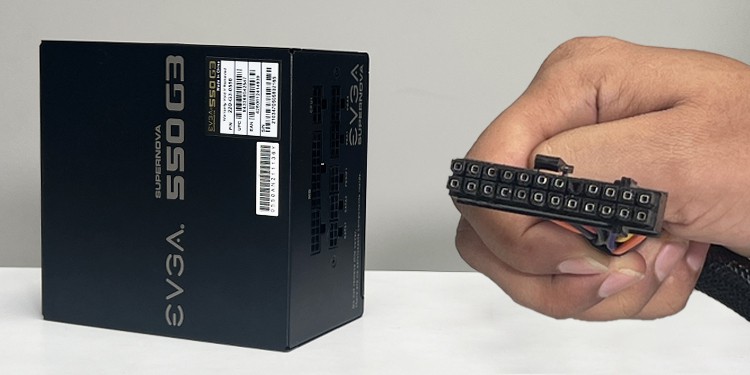
Below is the (20+4) pin ATX connector that got here with my EVGA Supernova 550 G3 PSU. I can effortlessly join such a connector to the motherboard header that has both a 24 pin or a 20 pin setup.

Here’s a fast overview of the ATX energy connector pinout.

Each of those pins on the connector have a selected function in your system. Let’s now dive straight into them.
+5VSB
This is the pin that provides standby energy to your system even when it’s turned off. It facilitates a number of helpful options like Wake-on-LAN and Wake-on-USB when your pc is in a low-power state. It additionally comes into motion if you first activate the pc. More on this later.
PS_ON#
This pin is especially used to activate the ability provide unit of your pc.
Technically talking, when your pc is related to the AC wall outlet, the +5VSB pin already begins supplying standby energy to the system.
So, if you press the ability button on the pc, a small voltage triggers the PS_ON# pin. As such, the pin will go low (connects to the bottom,) which in flip, indicators the PSU to activate.
Additionally, the PS_ON# pin can be extremely helpful for troubleshooting the ability provide. You can disconnect the ATX connector out of your motherboard and use a paperclip to attach the PS_ON# (pin quantity 16) to GND ( pin quantity 15.) If the ability provide is functioning correctly, it ought to activate.

PWR_OK
When the PSU is first turned on, it takes a short while to stabilize the output voltage. Once stabilized, the ability provide unit sends a PWR_OK sign to the motherboard, indicating that the ability provide is now secure and inside acceptable limits.
Your motherboard will refuse to activate if it doesn’t obtain the PWR_OK sign.
+3.3V DC
There are 4 +3.3V DC pins within the ATX energy connector that provides 3.3V DC energy to your motherboard.
If you examine the connector fastidiously, additionally, you will discover that one of many 3.3V DC pins (pin quantity 13) has two wires getting into it as seen within the image beneath.

While the primary one is for energy provide, the second exists there for sensing the voltage ranges. It is definitely used to calculate the distinction between the anticipated and precise voltage ranges. If any discrepancy is discovered, the PSU will make crucial changes.
+5V DC
There are a complete of 5 +5V DC pins on the ATX energy provide connector. As you may need already guessed, this pin significantly provides 5V DC energy to your system together with on-board storage disks like SSDs, and different peripheral units.
+12V DC
Unlike the +3.3V and +5V pins, there are solely two +12V DC pins on the ATX energy connector. The motherboard’s VRM (Voltage Regulator Module) converts this 12V to a variety of voltage ranges and provides it to different PC elements.
-12V DC
The ATX energy connector features a -12V DC pin that was chargeable for supplying detrimental voltage to legacy ports like RS-232 and legacy audio circuits within the early days. The pin continues to be built-in within the modern-day connectors to energy part of the PCI bus.
COM
There are a complete of eight COM pins on an ATX energy connector which act as a floor or reference level for all different voltage pins.
Not solely does it present the referencing, but in addition verify voltage fluctuations and helps mitigate {the electrical} noises and interferences.
NC
If you look carefully, you’ll find that one of many pins (pin quantity 20) is lacking out of your ATX energy connector. This is definitely the “No connection” pin.

However, there was a -5V DC pin as an alternative of the NC ones in the old fashioned connectors. It was sometimes used to energy the legacy ISA units like sound card, graphic card or a modem put in into the ISA growth slot.
CPU Connector Pinout
As the identify suggests, this connector is especially used to energy the CPU. It both has a 4, 8, (4+8,) or (8+8) pin configuration and the pinout differs relying upon the connector sort.
Here I shall be discussing the pinout for the usual 8 sort connector that got here with my EVGA Supernova 550 G3 PSU.

As you may see, the 8 pin CPU connector merely has 4 pins for 12V rails and 4 others for floor. If your CPU solely makes use of 4 pins, it is going to have two pins for 12V rails and the opposite two for grounding functions.
SATA Connector Pinout
The serial ATA (SATA) connector powers the SATA interface units, like a SATA onerous drive or SSD together with another peripherals like a RGB controller.
It has an ordinary 15 pin configuration in a particular L-shaped housing, to simplify the connection course of. Despite the 15 pins on the connector, you’ll solely see 5 wires getting into into the connector. Below is a fast overview of its pinout.

These voltage rails are used to produce energy to a variety of digital elements throughout the SATA units.
Coming to the voltage rails, the three.3V and 5V ones are usually used to energy low-power elements like a SSD reminiscence module and HDD controller.
On the opposite hand, the 12V rail powers the high-power elements like a spindle motor in your onerous disk.
PCIe Connector Pinout
Used to energy GPUs, these connectors include an ordinary 8 pin setup which can be usually removable into (6+2) blocks.

As you may see within the image above, the 8 pin PCIe connector has three pins for 12V rails, three for floor and the remaining two for voltage sensing.
The sense pins in these connectors are used to watch the ability requirement of a GPU in order that the ability provide unit can alter the voltage ranges accordingly.
On the flip aspect, you gained’t be getting the identical pinout in case your GPU makes use of solely 6 pins for connection. It, as an alternative, has two 12V rails, two floor wires and one sense wire. The remaining one might both have “No connection” or one other 12V rail relying upon the producer.
While in connectors from some producers, you could not get the sense wires in any respect. They simply have three pins for 12V and 5 pins for floor (in 8 pin setup) and three 12V pins and three GND pins (in 6 pin setup.)
Molex Connector Pinout
And right here comes the final one in our listing, the Molex connector. This sort of connector is used to energy the legacy units having Molex interface. For instance, a PATA onerous drive, or a CD/DVD drive.
Coming to its pin configuration, it usually has a 4 pin setup in a single row. But some variants might embrace 4 pins organized with two pins in every row.
Here’s a short overview of the widespread Molex connector pinout.

Check out more article on – How-To tutorial and latest highlights on – Technical News